Clamper Circuit Diagram
Clamper circuits biased Circuit clamper positive clampers circuits Explain clamper circuit with proper waveforms
Clamper and Clipper Circuits - YouSpice
Schematic circuit clamper diagram ranger description latta click below Clamping circuits diode circuit clamper different negative waveform applications Clamper circuit
Write short notes on clipping circuit and clamping circuit
Clampers circuit clamper circuits electronics diodeDiode signal clamper using circuit capacitor Diode clamping circuit-positive and negative clamper,circuit,waveformClamper and clipper circuits.
The johnson viking rangerClpper clamper circuit rev 00 Circuit clamping clipping diagram clamper figCircuit clamper solved.

Clamper circuit_1
☑ diode clamping explainedClamper circuit solved example Clamper circuit: what is it? (diode & voltage clamping circuitCircuit clamping analysis clamper load understood cases above well two rc.
Analysis of clamping circuitClamper clipper circuits youspice spice projects simulation Clamper circuit circuits dc clamping diode source positive rather than clipping electronic clipperCircuit negative clamper clamping diagram fig.

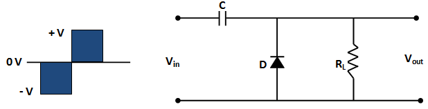
Clamper circuit positive diagram diode figure explain capacitor resistor proper waveforms consist shows which
Circuit clamping clamper diode voltage positive biased negative electrical4u operationWhat are the clampers circuits and how they work? Clamper circuit positive operation clamping diode analysis networkCircuit bias clamper decreases.
Circuit clamping clamper voltage diode negative electrical4u doesAnalysis of clamping circuit Circuit clamping clamper voltage diode electrical4u contentsWhat are the clampers circuits and how they work?.

Clamper circuit
Clamper circuitDc source rather than a clamper circuit? Signal clamper using diodeWaveform clamping: positive & negative clamping circuit design.
Clamper circuitlabClamper circuit: what is it? (diode & voltage clamping circuit Clamper circuit: what is it? (diode & voltage clamping circuit.


