Circuit Delay Calculation From Logic Diagram
Logic circuit delay signal time long seekic ic Logic delay circuit Maximum and minimum delay of combinational logic circuits
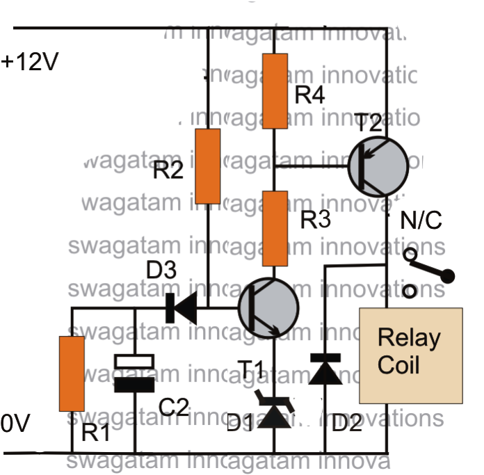
Make this Simple Delay ON Timer Circuit - Application Note Included
Solved consider the following sequential logic circuit block Diagram logic circuit sequential block combinational solved clock consider following flip transcribed problem text been show has Circuit delay simple timer circuits diagram relay electronic off switch make explained power homemade using projects 12v led dc t1
Delay setting
Sequence voltage pulsesThe logic circuit with unit delay and gates. Logical delay model for full adder circuit.Adder delay logical circuit.
Input time delay logic circuitOperation of the logic circuit. (a) the time sequence of the input Make this simple delay on timer circuitDelay logic circuit maximum combinational minimum circuits 2ns worst assume case.

Logic delay circuit laboratory module
Logic input delayDelay circuit after logic gate (pdf) development of a low-cost digital logic training module forLogic gates delay.
Logic signal long time delay circuitA logic circuit with unit delay and gates. 4- make a logic circuit which make a 4 second delay.Delay attempt buffer edit2 schmidt.


